LP-1 Multi-Function Logic Test Pen For Motherboard Testing and Maintenance
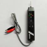
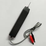
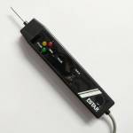
0 out of 5 stars
No review yetReady stock
NaN
As low as NaN
Worldwide shipping
Seller: Martview Shenzhen
ID: MV-241024WGUM41
Weight: 0.25 kg
| Qty | Price | Discount |
|---|---|---|
| 1 | NaN | |
| 3 | NaN | -3.1% |
| 5 | NaN | -4.7% |
| 10 | NaN | -7.0% |
Product details
Description
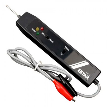
LP-1 Multi-Function Logic Test Pen For Motherboard Testing and Maintenance
The use of a logic pen requires professional knowledge. This product does not provide any technical support, please be careful when buying!!!
Features:
- LP-1 handheld multi-function logic pen can measure high and low levels, which brings great convenience to debugging and detection. It is a good helper for electrical engineers
- The logic pen is an instrument that uses indicator lights of different colors to indicate the level of digital level
- Using the logic pen, you can quickly measure the faulty chip in the digital circuit
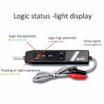
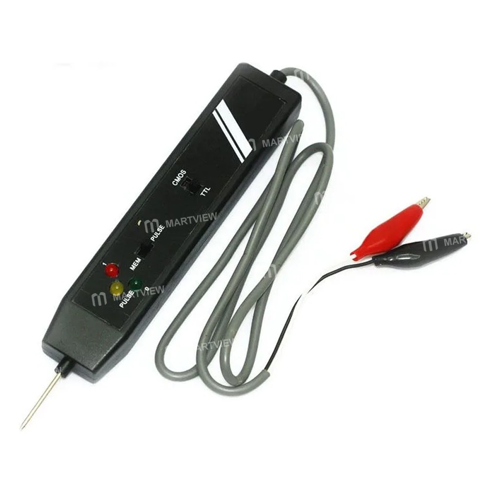
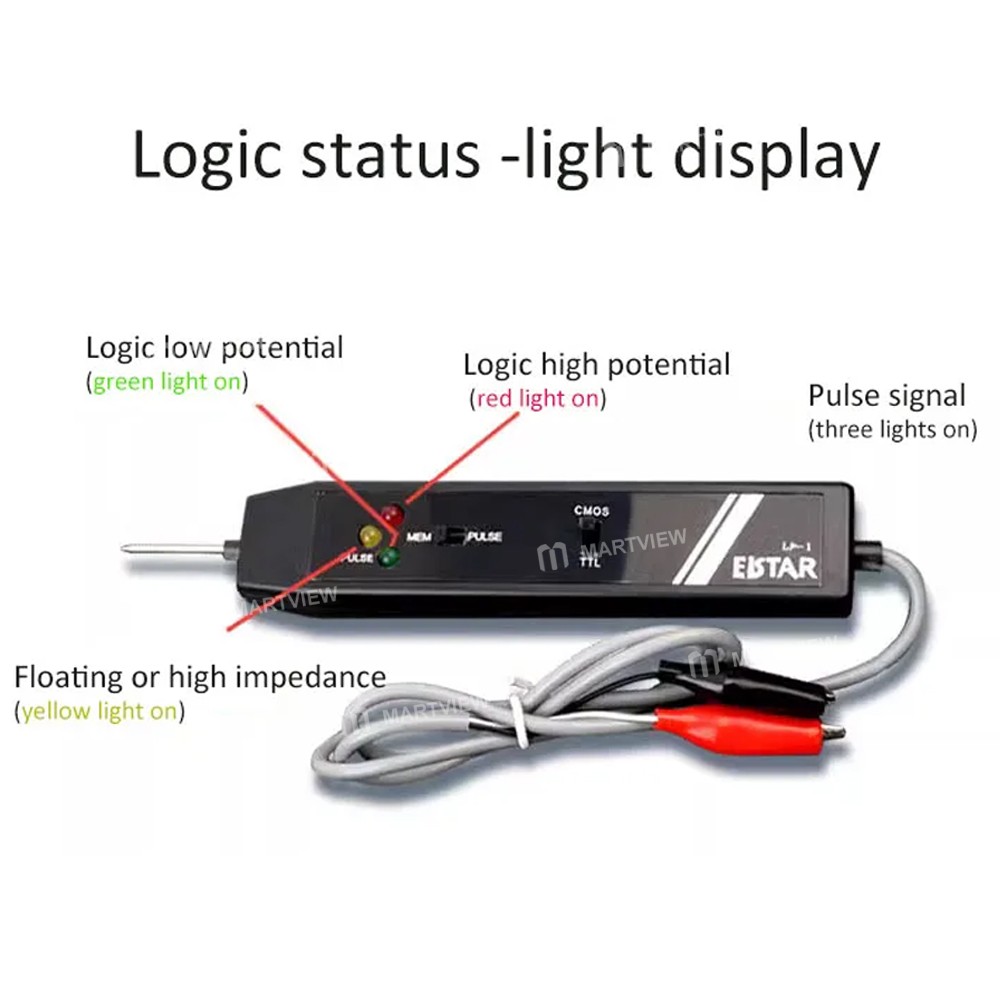
- There are generally two or three signal indicators on the logic pen: The red light generally indicates a high level; The green light generally indicates a low level; The yellow light indicates that the measured signal is pulse signal
- LP series logic pen is used to measure TTL level logic and pulse signals, its measurement bandwidth reaches 200MHz, and 10Hz, 100Hz, 1KHz, 10KHz, 100KHz, 1MHz, 10MHz, 100MHz for the demarcation of the frequency of the signal to be measured indicates that the unique nine-segment frequency acousto-optic indicator is clear and easy to remember!
- LP series of LED indicators with three colors and three flashing rates: blue indicates the measured signal frequency in the Hz scale.
- Blue indicates that the measured signal frequency is in the Hz frequency band, green indicates that it is in the KHz frequency band, and red indicates that it is in the MHz frequency band.
- The LP series buzzers have three tones and three on/off rates. The low tone indicates that the measured signal
- The low tone indicates that the measured signal is in the Hz frequency band, the mid-tone indicates that it is in the KHz frequency band, and the high tone indicates that it is in the MHz frequency band.
- The LP Series is also capable of capturing individual pulse signals, and it has full-time monitoring capability that is not lost, with LED indicators and a buzzer that responds to individual pulses.
- The LP-Series Logic Pens recognize the high impedance state (overhang) of the signal under test. red LEDs indicate that the signal under test is high, blue indicates that it is low, and green indicates that the point under test is in a high impedance state. The buzzer emits a medium tone at high level and a low tone at low level, while the buzzer is silent in the high impedance state.
- The Logic Pens are equipped with a unique precision anti-flutter test probe that can spot-test very small circuits and eliminate interference caused by human hand jitter.
- The signal and power supply of the LP series are "0.64 mm PIN" standard plug interface, can be connected with a variety of fixtures, such as its signal input terminal can be installed directly on the precision test clips, the whole clamp SMD component pins for long-term measurement.
- LP series logic pen input terminal can withstand 8000V static shock and ± 60V power shock, LP series can be used from 4V to 16V DC power supply power supply, its power terminal can withstand 2000V static shock, and has a power supply reversal protection characteristics.
Method:
- Clip the red crocodile clip on the positive terminal of the test circuit and the black clip on the negative terminal, noting that the voltage at both ends should not exceed DC 18V
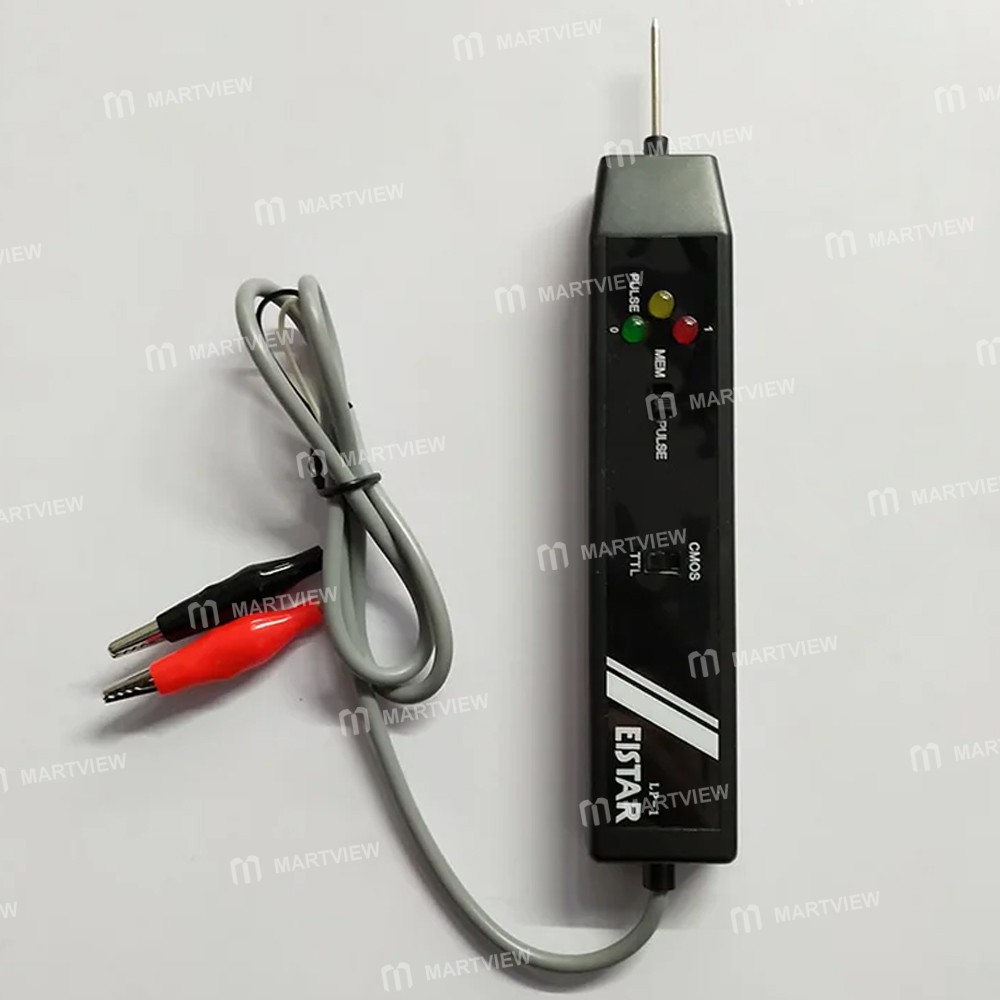
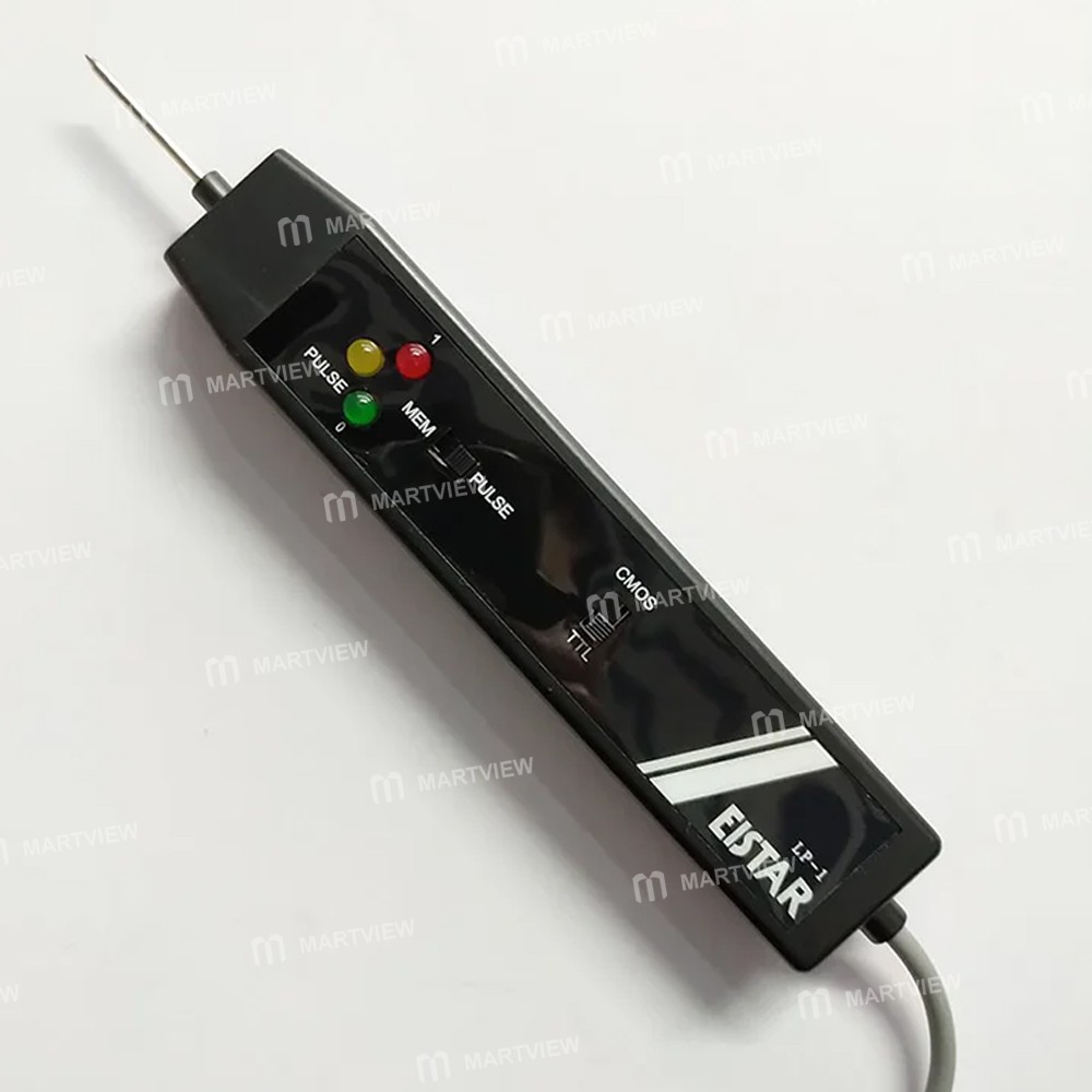
- If testing DTL or TTL integrated circuits, push the switch on the top of the test pen to the TTL side; if testing CMOS integrated circuits, push the switch to the CMOS side
- Then touch the probe of the test pen to test a point, the light-emitting diode on the test pen will show the state of the point as follows: all unlit: high impedance; red bright: high value (1); green bright: low value (0); orange bright: pulse
- If the test and storage pulses or voltage transients are, first push the switch under the test pen to "PULSE", one side of the probe to contact the point to be tested, the measurement of the light-emitting diode will show the original state of the point, and then push the selector switch to the "MEM" side, such as the test pen to detect the emergence of pulses or voltage transients, the orange tube will be lighted up with the aforementioned original state of comparison, that is, we can know the direction of the pulse.
- After use, the switch should be pushed to the "PULSE" side to reset.
Package includes:
- 1 x Logic Probe

Customer reviews
0.0/ 5.0
0
0
0
0
0


